Wednesday, October 6, 2021

My Salty's Hotel Project

Introduction

I'm going to try to build an HO model of a structure, Salty's Hotel, for the San Diego Model Railroad Association's HO layout, which is in located in the San Diego Model Railroad Museum in Balboa Park. The layout represents the San Diego & Arizona Eastern Railroad on the date April 24, 1949, based on information from a variety of historical sources. Salty's was an actual hotel that was near San Diego's Santa Fe depot at that time.

I'll be documenting the project in my Salty's Hotel blog page.


Wednesday, April 7, 2021

A Switch Machine With Little Depth For My Shelf Layout

I’m building a shelf layout 79.5” by 15.5” which will sit in a shelf area 11” high. Not much vertical space, so I want to minimize the layout base height.

I found a switch machine a height less than ¾”, from MRCS (Model Railroad Control Systems).
MRCS MP1 Switch Machine

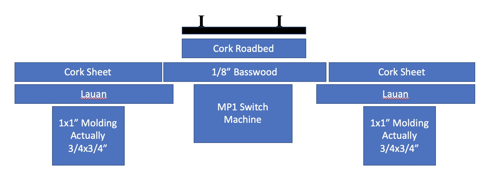
The base will be a sheet of 1/8” lauan glued & screwed to a frame of 1x1” molding, and a layer of 1/8” cork on top. Since 1x1” is in reality 3/4” on the sides, this results in a 1” high base, with 3/4” cavity underneath: Adding the roadbed results in having 9/8” to bottom of track ties.
Layout Base

I mounted the switch machine to a piece of basswood as a mount platform, and cut a hole in the lauan to provide a recess, then fit the turnout to the machine above that. The basswood was cut larger than the size of the hole.
Mounting The Switch Machine

Attaching the machine to the basswood using a piece of two-sided mounting tape allowed me to make sure the machine would fit, and to adjust as needed.

I positioned the MP1 at one end of the base so the connector rod to the turnout would clear.

MRCS recommended replacing the connector rod with something more flexible; I used a piece of .025” phosphor bronze rod from Tichy Train Group.

I then attached a piece of roadbed and a turnout to the other side of the basswood using Gorilla Glue. I could still adjust the machine at this point to fit the connector rod from the machine into the turnout and position as needed.

I cut out a hole in the lauan and cork sheet where the turnout would be located, and removed additional material from the cork sheet to allow the basswood to drop in.  

I could then glue the basswood to the top of the lauan where the cork material had been removed.

After adding more roadbed under the turnout, wiring it up per the instructions, and testing, I screwed the machine to the basswood to complete the installation.

This photo shows the wiring, with a SPDT switch to control the turnout. A switching wall wart provides 12V power. Alternatively, for demonstration, a 9V battery connection is available.
Wiring It Up

Finally, here is a video of the switch machine in operation.


Monday, March 29, 2021

Painting Trucks

I needed to paint the wheels and side frames on my S-Cab project switcher, and MR had a recent article in which Cody Grivno describes some techniques for this ("Tank cars for Jones Island", April 2021, pg. 26).

He spays the side frames with flat black spray paint, then applies Vallejo Oiled Earth Wash. For freight car trucks, he temporarily replaces the wheelsets with a spare set to mask the sockets, but for the switcher, the side frames were removed as part of the project, so I didn't have to worry about sockets. I also applied little touches of gray and rust washes here and there. The following photos, which I took of some switchers in the 1990s, show the kind of effects I used for inspiration.  (Note that the wheels on locomotives really aren't very visible behind the side frames).


For the wheels, Cody brushes on Dark Rust from Mission Models, which I didn't have. Instead I tried Vallejo Model Air Rust, which I think looks very similar to the photos in the article.

I used Microbrushes for this work, and I liked the results. I plan to use these techniques going forward for all my locos and railcars.

Summary of the techniques:

  • Use Microbrushes for brush painting.
  • For the wheels...

  1. If necessary, clean wheels with alcohol.
  2. Brush wheel faces with Vallejo Model Air Rust (no. 71.080).

  • For truck frames...

  1. If necessary, mask wheel sockets with spare wheelsets.
  2. Spray frames with Rust-Oleum Painter's Touch 2 Flat Black (no. 249127).
  3. Apply Vallejo Oiled Earth Model Wash (no. 76.521).
  4. Apply touches of Vallejo Dark Rust Model Wash (no. 76.507) and Pale Gray Game Wash (no. 73.202).
  • Update - I decided on another approach to try...
  1. Don't bother with spray painting.
  2. Use a micro-brush.
  3. Paint trucks using Vallejo Panzer Aces Dark Rust (no. 70.302).
  4. Paint wheels using Vallejo Model Air Rust (no. 71.080).
  5. Use Pan Pastels to add grime and additional rust.


Saturday, February 6, 2021

Wire Connection Techniques

I've never had too much fun connecting two wires, and finally looked on YouTube for suggestions. My normal connection technique has always been the pigtail (see diagram below): Strip the wires, hold them together and twist, and solder. Cover the result with electrical tape or shrink wrap. The result works but is not as nice as butt connections, and takes up more space in tight situations.

But butt connections are impossible for me, with only two hands and my fumble-fingers. Especially with small gauge wire.

YouTube provide a technique I really like. Sadly I've lost the link and can't credit the YouTube poster. First, don't forget to slide a piece of shrink wrap onto one of the wires. The idea is to start with a pig-tail, then bend it half-way, press, and solder. Then bend at the bottom and press against one of the insulated wires, and slip the shrink-wrap over the connection. After the shrink-wrap is shrunk, f you can pull the connection apart you're either the Hulk, or you need to be careful around Kryptonite. This method is illustrated at the bottom of the following diagram.

Wire connection Techniques: Pig-Tail (top), Butt (Center), And My Preferred Method (Bottom)

What's really nice about this technique is that the result is very much like butt connections in terms of compactness and esthetics.

The following photo sequence shows this method: The pig-tail connection with the strands twisted together; the middle bend; a bit of solder applied; the base bend down against the gray wire; and the shrink-tube slipped over the connection, prepared for a blast from the heat gun.


Sunday, November 15, 2020

Picked Up A Light Box For Model Photos

I ordered this light box from Amazon for taking pics of models.  Seems to work very nicely.

Amazon's description seems to include a number of aliases: Finnhomy Professional Portable Studio Photo Light Studio Tent, Light Box, Table Top Photography Shooting Tent Box, Lighting Kit, 16" x 16" Cube


Tuesday, November 10, 2020

My First Power On Board (POB) Project

I'm starting a new project: Modify an old SW1500 to use POB (aka Dead Rail). I'm going to try to use a Stanton self-powering truck to replace the original motor assembly. I hope this will create enough room to then add an over-the-air DCC and sound, along with batteries and a recharging circuit. I am expecting to not have enough room, but we'll see. For inspiration and guidance I'll be using a couple of posts from the Small Urban Rails website.

I'll be documenting the progress for this project in SW1500 Switcher With Power On Board (POB).


Thursday, August 20, 2020

Struggling To Build A Layout In Trainz

 I've gone through YouTube tutorials and have started to embed the various commands and buttons used by Trainz in my mind.  It's been a trial.  I've been trying to create a layout base, and was raising and lowering terrain and placing the base fascia, and the terrain wouldn't raise the way I wanted, or I couldn't raise it close to the base fascia without raising the fascia inadvertently.  The basic manipulation mechanisms are pretty straightforward, but there are a few hidden tricks that are needed along the way, and I really haven't found internet searches too useful ferreting them out - I've just had to puzzle them out myself.

Here are steps to use for layout building, to the point I've reached so far...

  1. Use the ruler to determine the basic layout base shape.  The ruler measures in real-world units, even if the route scale factor is set to a scale like HO.
  2. Outline the layout shape using base fascia.  This was a pain to figure out.  The facias are object splines - select the object category, then the object spline button, to get these.  Since I just thought they were objects initially, and didn't see them listed in the object list, I figured I needed to download them using the DS.
  3. Also, when placing the base fascias, it's best to line up the edges with the black or yellow grid lines.  It's really a pain raising the terrain to meet the fascia top otherwise, as I found out.
  4. I tried to download a DS layout that had some nice fascias, floors, walls, and layout features like turntables.  After over 30 hours of download, it finally finished with a failure.  Along the way there were a couple of other failures, Burt a retry would start the download again at the point of failure.  But the third one would not even try to continue.  The result is a route with a broken link indicator.  Now I was seeing items I was interested in my installed content, but by this time I'd realized the story behind fascia object spines, and it's possible I'd had it all along and didn't need to subject myself to the painful download attempt.
  5. The fascia I chose was "EMM Model Trainz Fascia Spline".  Working with fascia object splines is a pain.  If a fascia ends at the end of another, they will join and bend.  You have to choose the split button, then click at the exact right point to un-join, at the base of the fascia right at the join, which is hard to see.  Same challenge using the move function.
  6. Set the object spline height value to zero to prevent the fascia from raising up when raising the ground near it.  There was a lot of pain figuring this one out.
  7. In the topology function, use 5m resolution.  The vertical faces of the layout base are never absolutely vertical, and at 10m don't get sharp enough.
  8. Use the topology hight function to set the overall base height.  For the EMM fascia spline, and value of 60 seems the one needed to get the layout base to match the fascia height.