
Ye Olde Huff-N-Puff 27' On3 Tiffany Reefer Kit
I spent some time looking at the kit, and found the directions to be terse in the extreme. Also, there were some missing pieces, for example, the break stem support hardware. The directions didn't explain anything about how to install the door or brake hardware, or grab irons or brake wheel assembly. And the diagram provided was obviously for a more modern reefer model. So I spent some time trying my best to understand what instructions there were, and thinking about some of the things I would want to do and the order of doing them.
I found some websites that helped tremendously in puzzling out the kit, and providing examples and diagrams.
Modeling Early C&S Refrigerator Cars
DSP&P Refrigerator Cars: History, Photos, Plans (Ross Crain's DSP&P RR Pages)
Wooden Freight Car Project (NMRA St Laurence Division website)
The fact that Dave wanted the model cut down, as if it was a damaged reefer acquired and repurposed, meant that I would want to cut off the side with the brake wheel to get the 20' length, as if that had been the damaged side, so I didn't have to worry about some of the missing parts. Serendipitous.
I thought I'd build up the reefer section of the structure, and later build the dock and whatever else Dave decided he wanted. I cleaned the flash from the white metal parts, then used Floquil grimy black to brush-paint the door hardware, grab irons, and under-car items.
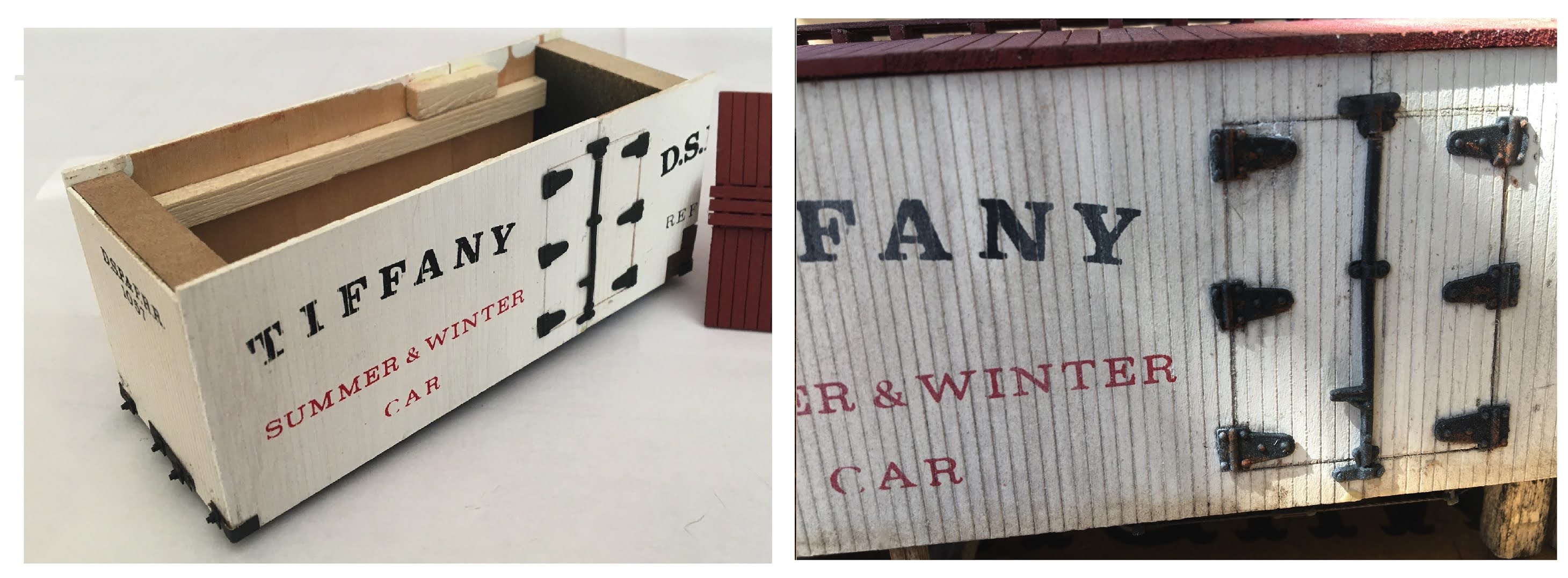
I found some drawings of the Tiffany cars online, and was able to make a black and white copy in O scale. To help guide how to cut out the doors, and to attach the grab-irons and hinges, I used Scotch tape to connect the two halves of one side of the car, and two-sided tape to attach the drawing to it, then cut off the excess paper.

I used a #78 drill for the grab iron legs, and cut through the lines of the door to mark them. I removed the drawing and tape and separated the two halves. Sadly, the door was off center; I must not have correctly lined up the car center to the connection of the two halves. So I cut down one side a little to make them even; the doors are thus be a bit narrower than the plan, but this wasn't noticeable, and the resulting reduction in the car's length didn't matter since I was going to cut the length to 20' anyway.
I used a needle to mark holes where the grab irons attached the side, and also the hinge locations to help locate where to glue them, then removed the paper and tape.
Using the door outlines I'd cut previously using the paper template, I used an X-Acto knife to score the doors, then used it's backside so that the scores were a little wider, but didn't cut all the way through. And using the needle-marks I'd also made with the template, I drilled holes for the grab irons using a #78 bit, inserted them, and used superglue where they stuck out in back to attach them. This exercise was academic, since this side was to be cut off to get the 20' length needed, but I wanted to install then anyway for practice. It worked pretty well. I used a trick I recalled from an MR article, and cut one of the grab iron legs shorter than the other. Then I could install the long leg first, and it was easy to position and insert the second leg, then push the grab iron all the way through. As the legs poked through the backside, I could also grab them with the tweezers from the back and pull until the grab iron were snug in front.
I cut the floor base to 20'. Then I glued the three large pieces that made up the roof support together at one end, in a way that allowed them to be placed in the small miter box, and cut the assembly to 20'. Then the three pieces from the unglued side came apart and were all the 20' length. I also shortened the floor beams and truss rod beams to 20', and glued on the truck bolster and floor supports to the floor base.
The roof was made by cutting down scribed wood material to the needed length, using the roof support structure as a guide so that there would be an overhang. The assembly of the roof and roof walk was IAW the kit instructions. Nothing in the instructions helped with the number of roof walk support boards needed, but the DSP&P website provided drawings that I used to decide on 2.5' spacing Similarly, the instructions described roof rib installation, and I worried about how to get the angle right from the top to the slanted pieces, until I looked more at the webpages and realized only the DRG version used them - the Tiffany version did not! The instructions didn't mention this specifically, and it was a relief that I didn't need to come up with a way to cut strip wood with angles. The kit was also missing the three boards needed to make the roof walk, but I found some HO 2x8" strips that looked like they would work. I glued the center strip on first, then used it and straight pins to hold the two side strips in place while they glued; this also gave me the small space between the strips that I wanted.

I assembled the structure car end blocks per the instructions, but did not glue the roof, sides or ends on right away. I wanted to paint the roof and bottom separately, to avoid having to do masking.
I noticed at this point the kit lacked the end beams that the cars had. I thought about trying to add beams, but didn't have the proper strip wood size to do so, so decided to just go with the kit's approach.


The fact that Dave wanted the model cut down, as if it was a damaged reefer acquired and repurposed, meant that I would want to cut off the side with the brake wheel to get the 20' length, as if that had been the damaged side, so I didn't have to worry about some of the missing parts. Serendipitous.
I thought I'd build up the reefer section of the structure, and later build the dock and whatever else Dave decided he wanted. I cleaned the flash from the white metal parts, then used Floquil grimy black to brush-paint the door hardware, grab irons, and under-car items.
I found some drawings of the Tiffany cars online, and was able to make a black and white copy in O scale. To help guide how to cut out the doors, and to attach the grab-irons and hinges, I used Scotch tape to connect the two halves of one side of the car, and two-sided tape to attach the drawing to it, then cut off the excess paper.

Side With O Scale Drawing From Internet Attached Using Double-Sided Scotch Tape
I used a #78 drill for the grab iron legs, and cut through the lines of the door to mark them. I removed the drawing and tape and separated the two halves. Sadly, the door was off center; I must not have correctly lined up the car center to the connection of the two halves. So I cut down one side a little to make them even; the doors are thus be a bit narrower than the plan, but this wasn't noticeable, and the resulting reduction in the car's length didn't matter since I was going to cut the length to 20' anyway.
I used a needle to mark holes where the grab irons attached the side, and also the hinge locations to help locate where to glue them, then removed the paper and tape.
Using the door outlines I'd cut previously using the paper template, I used an X-Acto knife to score the doors, then used it's backside so that the scores were a little wider, but didn't cut all the way through. And using the needle-marks I'd also made with the template, I drilled holes for the grab irons using a #78 bit, inserted them, and used superglue where they stuck out in back to attach them. This exercise was academic, since this side was to be cut off to get the 20' length needed, but I wanted to install then anyway for practice. It worked pretty well. I used a trick I recalled from an MR article, and cut one of the grab iron legs shorter than the other. Then I could install the long leg first, and it was easy to position and insert the second leg, then push the grab iron all the way through. As the legs poked through the backside, I could also grab them with the tweezers from the back and pull until the grab iron were snug in front.
I cut the floor base to 20'. Then I glued the three large pieces that made up the roof support together at one end, in a way that allowed them to be placed in the small miter box, and cut the assembly to 20'. Then the three pieces from the unglued side came apart and were all the 20' length. I also shortened the floor beams and truss rod beams to 20', and glued on the truck bolster and floor supports to the floor base.
The roof was made by cutting down scribed wood material to the needed length, using the roof support structure as a guide so that there would be an overhang. The assembly of the roof and roof walk was IAW the kit instructions. Nothing in the instructions helped with the number of roof walk support boards needed, but the DSP&P website provided drawings that I used to decide on 2.5' spacing Similarly, the instructions described roof rib installation, and I worried about how to get the angle right from the top to the slanted pieces, until I looked more at the webpages and realized only the DRG version used them - the Tiffany version did not! The instructions didn't mention this specifically, and it was a relief that I didn't need to come up with a way to cut strip wood with angles. The kit was also missing the three boards needed to make the roof walk, but I found some HO 2x8" strips that looked like they would work. I glued the center strip on first, then used it and straight pins to hold the two side strips in place while they glued; this also gave me the small space between the strips that I wanted.

Roof Walk With Pin Positioners
I assembled the structure car end blocks per the instructions, but did not glue the roof, sides or ends on right away. I wanted to paint the roof and bottom separately, to avoid having to do masking.

Kit Instructions On Left, No End Beam; Internet Photo Of A Model On Right, Showing Beam
I used #78 drill bit to install the queen posts. The kit provided a piece of thread for the truss rods. Installation was the standard "lacing" technique. After deciding where to drill the holes through the floors, I tried using the same #78 drill. Getting the thread through the holes, and the turnbuckles, was impossible due to fraying. So I used the old trick learned long ago from MR, and applied glue (I used ACC) to the ends of the thread, and like a charm it worked.
I used brake gear from Grandt Line (now San Juan Model Co.), and brass phosphor metal rods for the trusses. I had a lot of difficulty locating the pieces correctly, and aligning them. I also don't understand how one is supposed to make good connections between the plastic brake parts and the metal rods. I did the best I could with ACC glue. The end result is kind of embarrassing but it's good enough for what I'm trying to do with this model.
One good thing I figured out while trying to glue all metal rods and Grandt Line parts together was using a new "handi-hands" tool, as shown in the photo below. Also shown are the subassemblies before painting.


Using the Handi-Hands tool (left); Roof And Car Before Painting
The sides and ends were already painted, but I had to order the grimy black and oxide red spray paints and wait for them to come. I had used Scalecoat II spray cans for the Puebla Encante project and liked them, so I used them for this project also.
I wanted to hold the roof and body to paint them outside with the spray cans, so I made a holder by glueing a clothespin to the end of a paint stirrer. But there wasn't anything I could easily hold for the roof, so I also glued a short peg to the underside, which will be inside the car after assembly and won't be visible.

Handy Home-Made Holder For Painting
Next I glued the sides and ends to the car. I used hair pins for clamps, which I bent to allow the surfaces of the clips to lie flat against the siding as it was being held.

Hair Clip Clamps
After glueing one end, I trimmed the excess, then glued the sides and other end, again trimming as needed. On the "damaged" end of the car, I cut out a bit of siding, to allow a "repair" patch to be applied later.
I used NBWs with 2.5" nuts from Tichy for the end stay bolts, and taped the details to cardboard using double-sided tape. I painted the "patches" with Tamiya red-brown paint, and the other details with Scalecoat grimy black. I used double-sided tape to fix them to bits of cardstock, and taped that to a piece of cardboard for painting.

Metal Pieces Ready For Painting
After assembling the sides and ends, I used a brass strip from the kit to make end braces and plates. I used ACC to glue the NBWs to the brass braces/plates, and painted as shown above. Then I used ACC to glue the braces/plates to the car ends and corners.
Unfortunately I found that trying to insert the car into its slot in the deck, the NBWs would easily become detached. I decided to try good ol' Walther's Goo, and it seems to really work well - the bond is significantly stronger.
I applied Hobe-e-Tac from Woodland Scenics to the door hardware. After drying it provides a sticky surface to mount the hardware properly. Then with a little finesse the pieces could be lifted slightly for application of some ACC gel, and repositioned. Luckily the gel provides a bit of setting time so that the pieces can be adjusted a bit before they can't be moved.
To mount the car, I used simple cribbing under the truck mount, and some posts on the other side, to match the height of the deck surface.

Funky Cribbing Supports
I used Hob-e-Tac again, this time to attach these mounts to the car, so I could detach them if desired.
I made a sign to fit on top of the reefer, using scribed wood and strip wood. I painted the wood before assembly with Antique White from Apple Barrel. I applied an India ink stain mixture to the sign to highlight the scribing: 4 drops ink to 1/8 cup 71% alcohol. I used two applications of the stain, and liked the results.
I decided to try to use a home-made decal for the sign, so I purchased some clear ink-jet decal paper. I thought white letters with an old-west font, and a blue background, would convey the idea of blue ice and cold in general. After printing the decal in the printer, I used flat clear coat spray paint it to "fix" the ink, cut around the printed border leaving a bit of clear outline as a buffer, then applied it to the sign. I first stained the sign with the India Ink stain, and was quite pleased with how it turned out. Then, since I'm used to applying Solvaset to snug the decal down into the surface, I did so here. To my surprise, the result after the decal dried was not good; the edges where the decal ended were apparent, but worse, the edges tended to not adhere to the painted wood surface, and curled up in some spots. I think that what happened was that the inkjet ink was laid on top of the decal paper, and fixed with the clear coat. So the Solvaset would dissolve the underlying decal material, but not the clear coat, which might then lead to the curling. An actual decal would likely use ink specially formulated for decal use, so that the Solvaset application would succeed. I also found that using clear coat from ScaleCoat resulted in the ink coming off in the water when first soaking the decal. So I printed the decals again, this time using Krylon's flat clear spray, and printed so that the entire sign surface would be blue, leaving only the letters clear. Then I cut the decals to apply to each side of the sign, with the decal covering the entire surface. After drying, the edges still tended to curl, but now I could glue on the border strip-wood to cover up the problem. The following photo shows the printed decal, the painted sign, the various tools I used for soaking and applying the decal, and the result after attaching wire bracing.

Stuff Used For Making The Sign
The two popsicle sticks in the photo is the method I used to hold the sign vertical while drying. I put a piece of cardboard in my metal work-box, and used magnets to hold the popsicle sticks together, so that the sign could be placed between them and the sticks could be snugged together to hold the sign, with minimal contact between the stick edges and the sign they were holding.
In the past, when I've made models using real decals, the instructions provided in for the kits dictated the following: Paint the model, spray with gloss clear coat, apply decal with generous applications of Solvaset, apply spray with gloss clear again, and finally spray with flat clear. The results were marvelous. In future experiments with home-made decals, I will try this approach again. I'll also try using decals made with laser printers instead to see if that makes a difference.
The bracing was formed from .025" phosphor-bronze wire. I used NBWs with 6" O-scale square washers, and cut off the bolt end, then drilled a #78 hole in the center of the NBW. I then inserted one end of the wire pieces into the hole and used ACC gel to secure. Though not all the holes were exactly centered, this seemed to work out well. I then bent the NBWs to an angle so that they somewhat matched the angle of the reefer roof; if the ACC loosened I applied some more after bending. I applied Hob-e-Tac to the bottom of the sign and of the NBWs, and secured them to the roof. Here is the result.

The Sign
I'm really not satisfied with the look of the sign, but it is good enough at this point.
At this point, with much trepidation, I commenced to weathering the reefer. I first applied a new India Ink stain (7 drops ink to 1/8 cup water). Then I used Pan Pastels, following methods from Pete Steinmetz, MMR, as described in the PSR SD Div 11-Jul YouTube video (at about 1:24). I first experimented with scraps from the original kit reefer sides. DANGER WILL ROBINSON, DANGER! The India ink smeared the red lettering on the car sides! I tried spraying the car and roof with the Krylon clear flat first. This worked! I applied the diluted India Ink, and the lettering did not smear. The result was very nice - The ink darkened the paint a tiny bit, and also the slits between boards and the door outlines.
I then applied the Pan Pastels. At this point I'd still not glued the roof to the car, which made it easier to do the weathering. On the roof, I first faded the entire surface with Raw Umber Tint, then did a few individual boards using Neutral Gray Tint. I also used this to put on a couple of heavier streaks in a couple of places. Next I used Burnt Sienna Shade on a couple of random boards. I also applied Raw Umber to represent grimy dirt in a couple of spots, and under the locations where the bracing plates would attract accumulated dirt; the residue left by the Hob-e-Tac conveniently let me know where those would be.
For the car, I also first faded the entire surface using the Raw Umber Tint. This darkened the white Paint a tiny bit, but mostly served to fade the car lettering very nicely. I applied a bit of Raw Umber and Burnt Sienna Shade at the bottom of the sides and ends, to represent grimy dirt. I also applied a bit of Burnt Sienna Shade to the various metal pieces to represent rust.
I streaked some Neutral Gray Shade on the underside of the car, but it was hard to get the applicators in between the various piping and truss rods. I also applied Burnt Sienna Shade for rust on the piping and rods.
It all looked pretty nice at this point. In his clinic, Peter Steinmetz says that he does not fix his work with clear coat, but I don't want dusty pastels getting all over my fingers and Dave's layout, so I tried to put on a light coat of the Krylon Flat Clear. I've had the experience using chalks to weather, where they would disappear with the clear coat application, so I crossed my fingers. I think it turned out rather nicely...
Before Weathering (left) And After
Deck Construction...
To make the deck, I used an article from the February 1973 issue of MR, "Useful freight platform" by William Koteles. I drew a plan for the deck, designing it to wrap around the car on three sides. The size of the deck was constrained to the expected location on Dave's layout, 8.25x2.75". I planed on building it so that a small office could be added at one end if desired.

Deck Plan
I cut strip wood for the deck with the NWSL Chopper, using dimensions taken from the MR article. I distressed the wood using a tool I picked up at a hardware store that had dull metal blades spaced such that they would leave grooves when dragged along the wood. I think it might be a file card for large files.

"Gouger" Tool Used To Simulate Wood Grain
I stained the strip wood using India ink, 2 teaspoons per 1 pint 91% alcohol. Then I used the standard technique of taping wax paper over the plan, and using double-sided Scotch tape on the wax paper to fix the wood joists over the plan. Then I used wood glue to glue the stringer beams on them, using the plan to line them up.
I made a big mistake. The MR article describes a rectangular deck, but mine was not symmetric. I drew the plan as if looking down on the deck, so when I put down the joists and glued the stringer on top of them, so after the glue dried, flipped it over so the joists rested on top of the stringers. This caused the deck to be a mirror image! So I pulled the joists off stringers, and slightly sanded the edges where the glue had hardened, and tried again
This time I scanned my plan, then used the computer to make a mirror image, and printed that out for my template. It's tricky to print diagrams; the dimensions have to be adjusted to match the original. Luckily the program I used supports this.
Here are the joists taped to the wax paper, with the stringer beams alongside, ready to be glued to the joists.

Joists Are Taped Down, Ready For Stringer Beams To Be Glued
Here is the deck after assembly.

Deck
The stairs were built using LaserCut kits from Builders In Scale. I attached scribed wood to the deck to provide glueing surfaces for the stairs, and applied the India ink stain to the stairs and scribed wood.
There were a couple of problems fitting the car into the deck. There was a larger gap between the deck and the two car ends than I liked, and the gap showed that the alignment was a little off. Also, the stay bolts on the car ends stuck out enough that the car would not quite fit. I used a couple of pieces of strip wood to hide the gaps, and cut notches (which can be seen in the above photo) to allow the stay bolts to fit.

Hiding The Gaps
I used Hob-e-Tac to attach the piece of strip wood so that the car can still be removed from the deck. (It's interesting and frustrating that with this photo, I am noticing the gap where the car end siding meets the side siding. Oh well.)
Putting It All Together...
Here are the components of the model at this stage, including the deck (shown before weathering0...

Model Components, Ready For Weathering And Final Assembly
I left them separate for installation on Dave's layout, so that they can be removed later when I want to do additional work on the model. (For example, I may build a different, larger dock at some point if Dave would like change its location on the layout.)
I had a small diorama base from another model I made many years ago for Dave, and used it to mount the reefer and its dock so that I could take photos to send to him...

My Little Diorama, Showing The Model Ready For Dave's Layout
My son and wife tell me they think it's looks pretty good, and I'm inclined to agree!
Update...
I decided to try to add some NBWs to the deck supports, and while at it, change some of the bracing that wasn't originally a little short to be longer. I reused the original bracing material, but replaced the bracing on the dock side with scale 1 x 6 boards, for a better fit. I distressed the wood strips as usual, and stained using 8 drops to 1/8 alcohol. I scrounged my junk boxers for NBWs that seemed to fit, then marked their morning locations on the bracing and drilled holes for the NMB mount posts. The results looked very nice.
No comments:
Post a Comment