Under Construction
Introduction
I'm going to try to build an HO model of a structure for the San Diego Model Railroad Association's HO layout, which is in located in the San Diego Model Railroad Museum in Balboa Park. The layout represents the San Diego & Arizona Eastern Railroad on the date April 24, 1949, based on information from a variety of historical sources. The model will be of a hotel that was near the Santa Fe depot in San Diego's downtown at that time.
Salty's Hotel, as it was known, was a wooden structure. Next to it a smaller brick structure with stores was built sometime after the hotel was originally constructed. I'll be modeling both the hotel and the brick building.
Research
To prepare for this project, I received research material that had been previously prepared by the SD&AE club members. In particular, John Fiscella provided a wealth of material, including aerial photos, a street-view photo, and plan drawings which I'll use for the build. I also visited the San Diego downtown library (A wonderful place to spend some time) to pore over old city directories and telephone books. I also visited the San Diego History Center tbd.
The hotel was a tbd wooden structure. A small business "Salty's Naval Tailor" was located in the front. A San Diego "City Directory" was consulted for the years tbd to determine more information about Salty's and the businesses located in the brick building next to it. tbd - what did they say.
Here are notes that John F emailed me, from July and August 2021...
I have the perfect structure for you: Salty's Hotel. It's easy and I have the plans. In fact, they are attached (full HO scale). So are a few other reports and maps. But I don't have DIGITAL photos: only paper photos. I will make copies for you.
John F emailed me the following documents...
First, here is an overview of the portion the layout designated in San Diego's "Center City" area, where Salty's will be located. In this diagram, north is to the right. The hotel is shown in the bottom middle part of this diagram. It was next to a movie theater on India Street.
Overview of the "Center City" area
Next is a plan view drawing of the hotel and stores, plus some other buildings located along India near its intersection with Broadway. (John's drawing has a couple of errors; for example, it should be "Salty's Tailor", and the hotel was a wood frame structure, not stone). Again north is to the right.
Plan view including Salty's Hotel and adjacent stores
John also sent a photo that included a small sliver of Salty's, that he'd obtained from the SD History Center. He provided these notes for the photo:
This photo came to mind when you asked me about Salty's color. A piece of Salty's can be seen next to the New Tower Theatre. This is probably our best photo in terms of structural detail of Salty's. The overhead aerial is a lot worse and crude, and it does not even show an Edwardian house as such. That was only known from the Sanborn map.
This photo came from the San Diego Historical Society, and has a layer of imposed screening. If you try to improve it in PhotoShop using descreen, despeckle or Gausian unsharp, you get a horrendous mess of Moiré pattern, because the scanning process puts on its own raster screen and the Moiré pattern results from the combination-interference of the two.
While this photo is not the best for architectural resolution, it does show the clapboard and shingle construction of the roof (that was described on the Sanborn map of the block). It also shows that the hotel siding was a little darker than the theatre building, which was a light tan stucco (as observed in 1974). BTW, the date is obviously wrong at the bottom of the photo, because we see a 1941 Ford in the photo. So the date had to be post-1941.
In fact, the photo must be 1943 or later, since The Ghost of Frankenstein US release date was 1942, and Son of Dracula was first shown in the US in November 1943 (Kiss, Dr. Robert J. (2019). "Son of Dracula: The Release History". Son of Dracula. BearManor Media. ISBN 978-1-62933-430-1).
New Tower Theater and a bit of Salty's on its left -
the theater fronts Broadway; the hotel and tailor shop front India St.
Here we have the Salty's portion with lots of detail visible; the hotel and tailor entries, the signs, the roof trim and fire escapes, a vent pipe, and an anchor hanging next to the sign!
John also sent a 1921 Sanborn Map of the area. His notes: Salty's is called "Lodgings", next to the New Tower Theatre, Broadway and India Streets. On the 1921 Sanborn Map, it was called the "Portland Hotel".
Sanborn map trhat includes Salty's Hotel and Naval Tailor at Broadway & India, 1921
It turns out that the Library of Congress has Sanborn maps for 1921 and tbd on-line!
Before Salty's, the hotel was the Portland, as the first Sanborn map shows. The second labels it as "lodgings".
tbd - who is Salty?
Planning
I plan to construct the model using this nice modeling article by Melvin Perry, about modeling a Sears catalog house, as inspiration, as well as the multitude of other magazine and internet articles about scratch building that are available. I'll build the model based on the dimensions provided in John F's drawings. Variations will be introduced here and there as necessary. For example, I plan to cut the scribed wood material along the scribes as much as possible, which will partially dictate the model's height, placement of windows, etc. So we have
Width & Length (from John F): 3.70" x 8.75" actual, 27.55' x 63.44' HO. I plan to round to the next HO foot for the model's dimensions.
Height (from John): First and second floors, 2 5/16 inches; Attic 1 2/16 inches. From this we have the HO dimensions 16' 9"; attic 8' 2"; total height 24' 11".
After thinking about these dimensions, I realized the floor heights seem to be too low. It's possible that the dimensions John provided are accurate, and he told me they came from a 1921 Sanborn map he has. But since the floors have to include second story and attic flooring, this seemed like the room ceilings would be low. So I decided to take modeler's license and make the ceiling heights 8'. Some internet searches about buildings from the era confirmed 8' would be reasonable. Add another foot for the 1st and 2nd story flooring, we have 9' HO per story.
After cutting the walls, I tested placing the doors and window to see how things would look. Right away I could see that the first floor was way to short; the double entry door I'd wanted to use, from Alexander, was higher than the wall height. So I adjusted the first floor height to be 13' 6" HO. Similarly, the Tichy windows I was going to use would not fit in an 8' attic. I changed it to be 11' instead, after considering how the wall looked with the window placed.
The model will also include two siding's that are 4" HO wide, sidings narrower than the others, at the base of the attic. One of these narrow sidings can be seen in the photo that shows the Tower Theater and a bit of Salty's. It is assumed that another narrow siding like this was also at the base of the second floor. So the each story will be built with a 9' 4" HO height to accommodate the widths of the scribed board, plus 4" for the narrow siding. Luckily the scribed siding has a scribe at 9' (HO).
TBD - link for making cider/steel wool stain: https://startathomedecor.com/how-to-create-weathered-wood-with-tea-coffee-apple-cider-vinegar-and-steel-wool/
Givens:
Follow John's F plans as closely as I can, with modifications to allow for some constraints imposed by the construction materials, and other considerations.
Build the model with HO dimensions of width & length 27' x 64'. The component heights will be: first story 13' 6" (20 sidings, including the scribing-width foundation), second story 9' 4' (13 sidings), attic 11' (16 sidings), total height 34' (including the two 4" sidings).
Use techniques employed in in the Sears House modeling article referenced above.
Use Northeastern 3/32" x 1/16" x 11" scribing (332SCR116P), along with 4" x 4" (HO) wood strips for corner posts and the narrow sidings.
Use commercial windows and doors:
- Tichy #8010, 6 pane window, 42" wide x 36" high
- Tichy #8025, 2/2 double hung window, 30" wide x 62" high
- Alexander scale models #2406, Double entry doors
- TBD doors
Build the brick stores by kit bashing, or - use storefronts from tbd.
Interior detailed to a level sufficient for viewing through windows. Again, follow the methods used in Melvin Perry's modeling article .
Lighted interior.
Druthers:
Try to model the fire escapes using brass and other metal components, soldered.
Try to model the Salty's signs (visible in the Tower Theater photo) using EL material.
Researching The Businesses Near Salty's On Broadway & India...
I visited San Diego's main library downtown. It's a pretty swell place to spend time. On the top floor they have history and research material, including phone books and city directories. It turns out these are also available on the internet, but spending time in the library poking around is a lot more fun. Here is an example of the businesses along Broadway near Salty's, from a city directory, showing the business name and address, and sometimes the "proprietor".

.

City Directory: Broadway (left) and India
I used the directories for 1943, 1948, and 1950 to lay out the business information. (The 1949 directory was not printed). TBD - are these on-line?
Business information along Broadway & India, based on city directory information
It's interesting to see the evolution of the block during this time. It's also interesting how the name for Salty's changed, and somehow went back to the Portland from 1948 to 1950 - Not sure why that would be.
Checking out the footprint...
I wanted to see how Salty's would fit on the layout's block where it's located. I made footprints for Salty's and the businesses next to it, and for the Tower Theater and the businesses along Broadway, took them down to the layout, and put them in place. Looks like all should work ok.
Footprint on layout, at the corner of Broadway (bottom) and India (left). North is to the right.
Construction: Constructing the walls and roof...
(All dimensions following will be HO).
The Northeastern scribing needs to be cut so that the building is 64' long, with 4x4" corner posts. Also, 4x4" will be used for the single narrow siding between floors. Thus, each side wall will be formed using two sections of siding that are 63' 4" by 9'. Similarly, the front and back walls will be cut to 26' 4" by 9'.
The front and rear attic walls are triangular in shape. Their dimensions were approximated using the photo of Salty's next to the Tower Theater. I counted the sidings from the attic floor to the bottom of the window, from the bottom of the window to its top, and from the window top to the roof ridge. I took modeler's license to be able to cut to one of the siding edges. My goal was to generally reproduce the look of the wall. I also decided that the sidings would not be edged with a 4x4" corner post. From this I determined the base of the wall triangle to be 27', and its height to be 11'. This is taller than the value provided by John F, but after checking by placing a window on a drawing of the above dimensions, I think it looks better using the 27' by 12' triangle from John's dimentions.
I experimented with cutting out the windows. My friend Dave Balser let me borrow corner cutter tools to try out. They work like corner punches, and cut a nice clean corner. By punching the four corners, the windows can be cut using an X-Acto #11 blade. I experimented with this technique, with fairly good results, but it was hard for me to make sure it was aligned properly. Also, when close to the siding edge, the punch would push laterally on the siding, sometimes enough to cause unwanted breakage.
Next I experimented with another technique I've read about over the years - drilling small holes in the four corners, then scribing from hole to hole. I felt much more comfortable using this technique, and the results seemed cleaner. So I used this approach during the project.
The drill I use is a small cordless drill that I got from Micro-Mark a while ago. It's not as well-made as others that are out there, I would guess. The drill bit wobbles a little when I drill, for example. But I really like the drill for easy set-up and use, and it certainly does well for the small jobs I use it for. Among other things, it came with a set of metric bits, and I used the 1.5 mm bit for this job.
Corner cutter, drill and results
The steps that worked for me, to cut windows and doors, were- Measure and draw shapes on wood scribed side, using a pencil. Try to place so that horizontal cuts can match scribe lines whenever possible.
- Punch depressions at the corners, to help position the bit.
- Drill holes in the corners using a 1.5 mm bit.
- Cut the wood from start to end hole, along the pencil lines. I like to position the wood so that the knife blade are pulling along the pencil lines, nearly straight toward me.
- Scribe the vertical cuts first.
The drill holes provide nice start and stop points for the cuts. Using a straightedge, start with a very light cut, and cut about three more times lightly. This should result in a clean initial cut. At this point the straightedge is not really needed any longer. Then start cutting more deeply, initially with short cuts near the end, and as these go through the wood, start cutting closer and closer to the beginning of the cut line. This approach helps to eliminate blade wander as the cut is made.
Here are the measurements for the window and door cutouts, and the tools used for cutting...
TBD - add doors - Window and door cut dimensions
Tools used for cutting windows and doors
Here are the walls after doors and windows have been cut out.
Walls with openings for doors and windows
1/8 x 1/2 inch vertical strips were glued horizontally to the inner walls between the window openiings, to prevent warping, and the inner sides spray painted black to provide light blockage.
I used the stain as described above, and then painted using Apple Barrel Canary Yellow craft paint. I'm not sure the staining step was necessary, but it might have created a slightly darker effect. I also spray painted the windows and doors with a Rustoleum brand antique white primer. This was a mistake because the type of primer created a slightly mottled surface. I decided it was good enough, however.

.
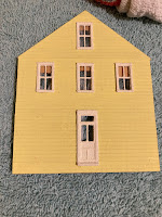 Walls after staining, and after painting
I glued in the window and door frames, added the clear plastic "glass" provided with the Tichy windows, and then fashioned curtains using tissue paper. I also added some "window shades" by cutting rectangles from a manilla envelope and gluing them on. Finally I glued the walls together, using a rubber band to hold the assembly together. The corner bracing strips were used to glue them, spacing the ends to allow 4x4 scale inch corner beams to be attached later.

 Windows, doors, curtains and window shades
I fashioned the roof using .040" styrene, with triangular bracing. I used Builders-In-Scale City Shingle material for the roof, staining it with diluted India ink before cutting the shingle strips and laying them on randomly.

The roof with bracing | 
Staining the shingle | 
Test fit
|
Mounting the LDR
i planned to use a Light-Dependent Resistor (which detects light level) as part of the model's lighting control. I drilled two holes using a #68 bit, just above the rear bottom deck, so that the LDR's leads could feed through the inside, and bent the LDR upward. Wood planking will be glued around the LDR so that it looks like a box.
LDR mounted via holes in wall | 
LDR bent up, with deck underneath |
Rear Deck
I made the lower and upper decks from scribed wood, supported with pieces of strip wood, and the upper deck supports and railings by harvesting styrene vertical supports and railings from a Walther's oil loading platform kit. I drilled holes in the lower platform to accept the tabs at the bottom of the support legs, and in the upper deck to accept the tabs at the bottom of the railing legs.
Building the rear deck structure
Initially I tried fashioning the vertical supports and railings from strip wood, but my attempts didn't look very good, and seemed very fragile. Luckily the kit had some pieces that fit nicely with a bit of strip wood shimming. I painted the supports and using Rust-Oleum Antique White, which nicely matches the antique white craft paint used on the rest of the model.
Interior and Lighting Control
I built view block structures tto look like interior rooms using .060" styrene sheeting, and used pieces of painted balsa wood to fashion beds, dressers, desks, tables, etc. Some commercial products were also used, such as the window blind material that came with the Tichy windows. I used ink-jet printed doors and pictures to decorate the walls, and bits of tissue paper for curtains. Not super detailed but good enough to look reasonable if someone peeked through the window of a lighted room.
Interior "rooms" and "furnishings",
with the Pico sitting on the second story ceiling (left)and a NeoPixel strip glued to the
underside; The first story ceiling also has a strip; The individual NeoPixelson these are
energized by the Pico to light the rooms below
The lighting control was accomplished using a Pico microcontroller and a Python program. I wired the Pico to the various porch light LEDs and the LDR, and to NeoPixel strips glued to the ceilings of the two floors (as can be seen in the photos above). The Pico processor mounted on a piece of stripboard was mounted on top of the second floor ceiling under the roof (again, see the photo above). Mini-connectors from TBD were used so that connections could be disconnected, and the floors and roof built to be taken apart as necessary, to support maintenance of components if it becomes necessary. The Python program energized the LEDs and NeoPixels to simulate people turning lights on and off in the rooms, using the LDR to detect if it was daytime or night-time. The front and rear porch LEDs were inserted into N-scale light fixtures and mounted below the upper deck in the rear, and under the porch roof in front.
The power provided for structures on the SD&AE layout is 12V, while the Pico input is 5V. I bought a 12V DC switching wall wart for testing, and used barrel connectors to (I asked the SD&AE club folk to install a barrel connector for the model when installed on the layout.) I wired in a 12V to 5V "step down (buck) converter" to supply the power level the Pico wants.
Signs
Some signs are shown in the prototype photos, including one for the tailor shop in the 1940s photo, and a sign on the roof from the earlier photo. Since I didn't have a good picture of the hotel showing any signs advertising the rooms available, I used modeler's license to add two "Rooms" signs on top of the roof, like in the older photo. For the tailor shop sign, I got help from Wayne Pierce to use the original photo, which luckily was dead-on so I didn't have to do much to fix perspective. (Wayne has a great model railroad in San Diego, and a swell website -
The Minieton RR and Lumber Co.) Wayne suggested printing at high resolution using "Epson Premium Presentation Paper Matte" paper. I was trying to print on normal copy paper, and the using the higher quality paper made all the difference. Wayne suggested using a "navy blue" color to align with the tailor's clientele.
The tailor shop sign
I fashioned two "Room" roof signs, which were inspired by the roof-mounted sign seen in one of the prototype photos. I kept them simple, and printed in black and white like the original. I weathered the signs a bit with Pan Patels grays and some browns.
To mount the signs, I used .032" and .025" phosper bronze rod from Tichy. I soldered support structures from the wire, glued to a price of .040" styrene sheet, I used two-sided tape to adhere the paper signs to the styrene.
The tailor shop sign mounted using Phosphor Bronze wire
Fire Escapes
A bit of the fire escape above the front porch is visible in the photo above, and some photos to follow show more of both front and rear escapes. I built these from a Gold Medal Models 87-01 Standard Fire Escape kit. These are etched metal kits that are bent into shape, and I really like the way they look. I used ScaleCoat grimy black and some Pan Pastels for painting and weathing. I should have put a coat of Tamiya primer on first; the black paint doesn't adhere as well as I'd like and required touch-up after being attached to the model. I drilled small holes in the model for the fire escape mounting pins, and used gel Loctite super glue to fasten.
Roof Trim, Rain Gutters, and the Smoke Stack
The prototype photos of the hotel show it had a trim that I emulated using a Grandt Line (now San Juan Models) roof trim product. I used the Rust-Oleum Antique White rattle can paint again, after a spray of Tamiya gray primer.
Roof trim
I tried to use the internet to get ideas for modeling the rain gutters evident in the prototype photos, but didn't have a lot of luck. Then I thought of my old favorite, 700 Tips TBD. which suggested using TBD with small bits of paper for the ends. I glued the gutter and trim to the roof using Walther's Goo, followed by an application of Loctite CA glue, which seemed to provide a surprisingly strong bond.
I fashioned downspouts using .032" phosphor-bronze rod, with .025" rods soldered on for supports to insert into holes drilled in the hotel's sides.
Downspouts are 032" rod soldered to .025" rod supports
The smokestack was built using 3D-printed pipe pieces from Model Tech Studios, glued together and cut to the needed lengths. Again, I used .025" phospher-bronze rod for horizontal support, inserting them in holes drilled in the pipe, and in the hotel walls. I glued a cap fashioned from solder to the top of the pipe smokestack, and painted it all using Grimy Black rattle cans from ScaleCoat.
Model Tech pipe components | 
Pieces cut and glued together, with mounting wires attached |


 .
. 


 .
. 


No comments:
Post a Comment