Under Construction
I've decided to try to modify an Athearn SW1500 switcher to be POB (aka Dead Rail). My inspiration, and hopefully guidance, is from posts on Rich Erwin's Small Urban Rails website:
Radio Active - Rich's initial post about how he converted a switcher to POB
Radio Redux - An update
I'm going to try to use a Stanton self-powering truck to replace the original motor assembly. I hope this will create enough room to then add an over-the-air DCC and sound, along with batteries and a recharging circuit. I am expecting to not have enough room, but we'll see.
I'm also going to try using Neil Stanton's S-Cab for the radio control. This choice was made based on the following "givens & druthers":
- I want the components fit in the body cavity of the Athearn SW1500, which is pretty small.
- I want to be able to power the components via magnetic reed switch, and not from an on/off switch mounted somewhere on the switcher.
- I would like the battery to be charged from track power, and not from a plug that would require accessible mounting.
The S-Cab appeared to have all these features available, though I was a little disappointed that the throttle was not available with a knob for speed control, which I would have preferred. (But when I received the S-Cab components, I was very pleasantly surprised at how much I liked the throttle's slide speed control.)
My first step was to gather possible candidates for the project. I rounded up all the SW1500-type switches in my possession, and was surprised by how many I've collected over the years.
My Stable Of SW1500-type Diesel Locomotives
In the photo, three Athearn locos are on the left, two Life-Like locos are in the middle, and one Revell loco is on the right. The Revell is obviously pretty old. I've often seen indications that these are not truly models of SW1500s. For example, Small Urban Rails indicates the Athearn is actually a SW7. But they all look like the locos I remember that worked the West Anaheim yard when I was a kid. The Life-Like SP is the nicest model, with lots of detail and see-through running boards etc. I'll be using the Athearn switcher that's missing the rear trucks for my project.
I wanted to compare the innards of the three manufacturer's locos and took the shells off. For the Athearn, it was pretty simple: hold the loco right side up, use fingernails to spread the plastic fuel tank fascia in the middle of the model to disengage the two tabs holding the shell to the frame, and gently shake up and down until the frame drops down and off. The Revell was harder. The frame has two small round nubs that insert into small holes in the frame. I had to insert the blade of a small screwdriver to spread the body on ones side a bit to disengage the nub, then pull down to keep it disengaged. I repeated this on the other side. The frame fits very snug into the body, so I had to use a flat-blade of some type to leverage the body off, a little at a time, first front then back, until it finally came free of the frame. The Life-Like was impossible: I look and looked and for the life of me couldn't figure out how to remove the body. My searches of the internets also was a big fail. I tried to remove the front coupler, but after removing its screw, I couldn't get it out of it's pocket, and after replacing the screw, the coupler no longer returned to the center position. I also damaged a couple of the fragile details while fooling around trying to figure out how the body attached to the frame. I gave up.

Bodies Removed To Reveal Frames Assemblies: Athearn (left) and Revell Switchers
It was interesting to see the old Revell switcher's innards. The frame is plastic instead of metal, the motor drives only the rear truck, and it has a very large weight over the front truck.
I had originally planned to carry out my project using an Athearn switcher, and chose the one that was missing its rear truck (left front in the above picture), which would mean one less thing to have to figure out how to detach.
I wasn't confident using the NWSL website information is very detailed in explaining how to order the correct Stanton configuration, which takes into account wheel diameter and distance between the truck's front and rear axles. But I wasn't confident about figuring it all out, so I boxed up the old switcher and mailed it to NWSL with a note asking for them to return it with the compatible Stanton Drive (SD). They were kind enough to do so! I did warn them about what I was doing beforehand via email. I really appreciated their willingness to do this, and the extra assistance from Holly Storm.
Here are the various components for the project. It includes an unpowered Stanton truck I decided to use to replace the second truck. This photo actually shows the other switcher that wasn't missing it's rear truck.
Athearn Switcher, The Powered And Unpowered Stanton Trucks, And The Shipping Paperwork
After taking the shell off, I removed the truck and motor from the frame. The truck came off by pushing together two half-circle tabs that then need to be pushed down through the mounting hole. A bit of forcing was necessary to get the drive shaft free from the truck's gear box coupling. The motor is mounted using two plastic rods that press into the metal "fuel box", and after pressing the rods up from below using the handle of one of the tools I have that was a little smaller in diameter than the rods, I was able to get it to the point where I could pull the motor free from the frame. I also inadvertently removed the loco's front lamp support, but it probably would have had to be taken off anyway.
Here is the switcher shell (again, I actually used the other one I had), along with the frame, motor and truck assembly after their removal. It also shows the two SD instruction sheet.
Athearn Shell & Frame After Removal Of Motor And Truck;
The Two Stanton Drives And The Associated Instructions Are Also Shown
I was originally going to grind down the model's metal frame, per the Small Urban Rails lead, but after trying to figure out how I was going to cut it down properly, and then attach brackets to mount the SDs, I thought about trying fashioning a new frame using .060" styrene instead.
I sat the model's body on my scanner and made a copy, which provided an outline of the shape I needed. I measured the length and width, and made cutouts where the body's fuel tanks and a few tabs were located. I extended my frame in the front where the coupler housing would mount, but in the rear I did not, in order to clear a body tab used to mount the cab; I'll fashion a mount for the rear coupler that clears this tab.
Taking measurements from the copy I'd made, I drew lines for a template on heavy-weight project paper (like what is used for note-cards), and cut it out. I fit and adjusted the template until satisfied, and noted the dimensions. Then I taped the template to a piece of the .060" styrene and cut it out. Here is the result, fitted into the SW1500's body.
Starting To Build The Styrene Frame
I used the original model's frame to measure the locations of the drive mounting holes, and marked them as can be seen in the photo. Per the SD instructions, I drilled 4mm holes, test fit the drives with the frame and body, and placed the loco on a track. I placed another Athearn SW1500 on the track to compare the end heights, especially lining up the running board steps between the two locos. As expected, the body rode too high on the initial frame. I measured the height differences, which was very close to .060". So all I needed to do was add another layer of .060"styrene sheet to the first piece to obtain the proper height.
I cut holes in the frame to accommodate the SDs, so that the frame rested lower when placed on the trucks. I then fashioned another piece from .060" styrene sheet, that would fit up into the loco's body cavity, and used Walther's Goo to glue it to the top of the first piece. I again measured and marked the SD truck mounting locations and drilled 4mm holes in the new layer.
The Frame After Holes Cut To Allow Lower Fit Onto Trucks, And With Second Layer Attached
Now placing the loco on the track with the SDs mounted, the height is very close to the original model's:
However, the photo exposes a significant flaw: The wheels on the rear are too close to the loco's end. It's apparent that when the truck frames are attached to the SDs, they may foul the end steps and not be able to rotate properly. They probably won't look right either. Major bummer.
I put another SW1500 on my printer and made a copy. The result showed enough detail from the bottom to (1) allow me to determine the location needed for the SD mount, and (2) allow me to position my plastic frame so I could determine where the holes should have been located. They were both quite near the original holes, of course, and this caused great difficulty trying to drill the new holes, since the drill bit would want to drift into the old hole once it got deep enough. I ended up getting the new holes partially drilled, then used the bit to further ream out the holes to allow the SD's 4mm post to be positioned in the correct location. The result, as a consequence, was very crude, causing despair. But when I test assembled the SDs onto the plastic frame and the model's body, I was pleasantly surprised that things looked pretty good, due to the flat surface of the SDs around the mount post. I do have some ideas about how to "fix" the mount hole problem later.

Frame With Enlarged Mount Holes - Sadly Crude
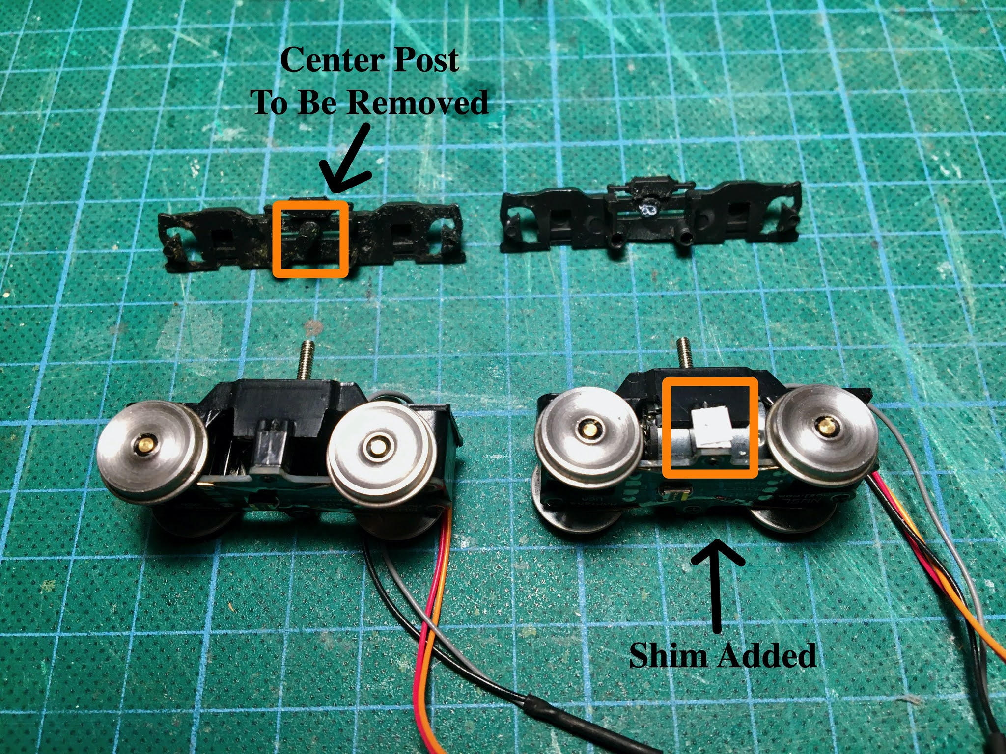
Next I tackled the truck frame mounting. First, per the SD instructions, I cut off the coupler pockets. I then pried truck frames from the old Athearn model, and since it only had one truck, another one also. I examined the truck frames, which have plastic protrusions used for attaching to the Athearn trucks. After fiddling around, I determined that I should start by removing the truck frame's central rod. I cut it off as close to the base as I could with rail nippers, then filed the resulting nub down flat as much as I was able. Some more fiddling showed that a pad on the SD's side could be used to attach to the truck frame at the nub's location, if a shim was added. The SD's instructions indicated styrene glue could be used, so I laminated two pieces of .5mm x 4mm styrene strip material to make a 1mm thick shim, and glued it to the powered SD. Here is a photo showing this work.
Left: Before - SD And Truck Frame
Right: After - SD With Shim Added, And Frame With Center Post Removed
I attached the frame to the SD and it seemed to work, but I could tell the brake shoe on one of the trucks might be rubbing. The tolerance is quite small for these shoes.
I put the SDs on a test track, placed the frame over them, and set some on some weights. The assembly moved fairly nicely, but there was a noticeable lurch. I pried the frames back off the SDs - they separated nicely from the shims - and tried again on the test track. Now the movement was nice and smooth. So indeed, the brake pads were rubbing the wheels on one side. When I try to mount the frames again, I'll have to figure out how to ensure separation between the brake pads and the wheels, which is going to be difficult.
The model's body includes representations of the fuel tanks. These hang down in the middle of each side of the body. Each includes a small slot that accepts a small tab on the metal frame; to mount the body on the frame, you pull the sides apart so that the tanks can slide over the tab, then let them slip into the slot, securing the body and frame together. I decided to make use of these slots by slipping a strip of styrene through them, to hold the plastic frame up into the body. I glued a metal car weight on the top of the plastic frame using Goo, then used an old Kadee tap and drill so that I could screw a bolt through the plastic strip and into the frame, thus securing the frame to the body.
The Plastic Strip Is Shown After A Clearance Hole Has Been Drilled.
Also Shown Are The Car Weights And Kadee Tap/Drill Packet Packet
Car Weight Attached To Top Of Frame (Using Goo)
The Frame Is Nestled Into The Body Cavity, And The Plastic Strip Spans The Car Width, With The Strip Ends Instead Into the Body Attachment Slots, And Secured With An 0-80 Bolt
Next I started looking at mounting the couplers. I put the styrene frame on the Stanton trucks and placed it on a track, then put another SW1500 on the track next to it, to compare heights of the bodies and coupler pockets. I measured and tested with different widths of styrene and ended up with the following for the coupler mount: First, a layer of .5mm styrene strip, then asa piece of .060" styrene sheet, and finally a piece of .064x.25" brass strip. It looked like this combination would get the brass strip up to the level where it could fit into the body coupler cavity, to match how the coupler mount on the Athearn's cast metal frame fit. Here is a photo of the styrene layers cemented to the frame, and the two pieces of brass that will go on next.
Mounting the couplers - Styrene Strips Glued in Place, And Brass Pieces Cut
I wanted to attach the coupler box to the brass pieces so they would be flush at the end where the coupler sticks out. I tried using double-sided tape to attach the box to the brass, but it wouldn't adhere, so I just ended up doing the best I could to hold the box against the brass and mark the brass through the coupler box hole with the tip of an X-Acto knife. I realized I would have to notch the styrene pieces that the brass pieces would glue to, to proved clearance for the coupler mount bolt.
I used Goo to glue the brass pieces to the styrene frame, checking that the end of the brass piece was flush to the the edge of the body's coupler cavity, then used the #246 Kadee drill/tap set, compatible with the Kadee #148 coupler set. I used a power drill for the hole in the each brass piece, then a hand0-drill to tap. I held the piece of brass in a vice for this work.
Brass Piece Held In Vice, For Drill/Tap Work
This allowed me to mount the couplers, then check them for proper height using a Kadee coupler gauge. Success!
Couplers Mounted Per Kadee #148 Coupler Set Instructions
I had ordered the S-Cab components, pestering Neil Stanton with a number of newbie questions, which I've copied to the end of this post. He was patient with me and prompt with his responses. I emailed him an initial order attempt using the form and information on the S-Cab website. I found out that using a "motherboard" with components attached would make the installation a lot easier, and Neil had a "short" motherboard that would fit nicely in the SW1500's body cavity. He sent me back an updated and corrected order form for me to use, and I went ahead and placed the order.
My S-Cab Order
When the S-Cab components came in, I set them up for an initial test per instructions on the S-Cab website. Success! I turned on the throttle, and then was able to use the magnetic wand that came with the order to turn on the S-Cab components mounted on the Motherboard (MB). Using the function keys, I was able to activate the lights, bell and horn, and watch the wheels turn on the powered truck when advancing the speed slider.
Wired Up Per Instructions On S-Cab Website For Initial Checkout
At this point I started thinking about trying to put everything together in a preliminary test. I mounted the body on the frame and was immediately faced with a major problem. When the SDs were mounted in the frame and the body attached, I could see by comparing the loco with another one, side by side, that there was too much separation between the tops of the truck wheels and the bottom of the loco body.
The Body On My Styrene Frame (Right) Sits Too High, Compared To The Original Model
To fix this, I would have to lower the frame on the trucks, which would necessitate removing some of the frame mounts and enlarging the cavity for the truck to fit up into. But at the ends, this would mean removing part of the frame that supported the body. To compensate, I needed "tabs" that would extend into the coupler cavity in the body, which my original frame did not have.
So I had a choice - Start over from the beginning to build up a second styrene frame with the additional "tabs". Or, switch to Plan B - Make use of the original Athearn metal frame
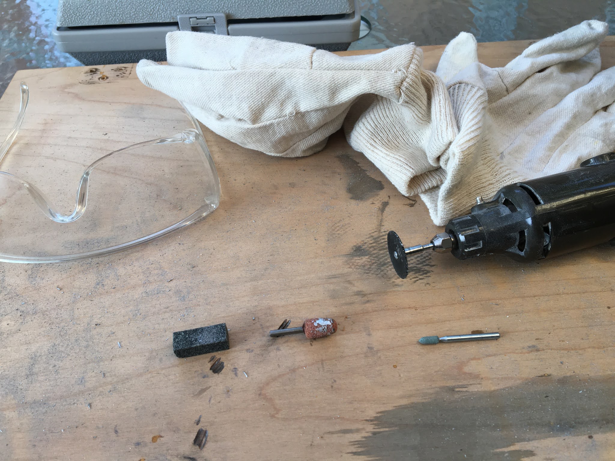
I decided on the second option, since I'd grown weary of cutting styrene pieces. It meant I would have to cut and grind some of the Athearn frame, in order for the SDs to fit (as warned about in the "small urban rails" website). But I decided to pull out my five decade old Dremel tool and have a go at it.
Dremel With Cutting Wheel, Grinding Tips, And Honing Stone
I did the work using a cutting wheel and grinding stones. I soon found that the stones would fill with the soft casting metal material and not grind. By running the Dremel and holding a "honing stone" against the grinding stone tips, the metal material would slowly be removed, and I could continuer using the grinding stone again for a little while. But they didn't remove much material between honing, and I found it was a lot easier and productive just using the cutting wheel.
Using the information provided in the Small Urban Rails website, I needed to enlarge the forward (hood) and rearward (cab) cavities to allow the SDs to fit up in and to rotate, but I had no idea how much. I started with the hood end, where the body cavity is wider, and removed material up to ridges on the frame top that were parallel to the surfaces where the body rested. I left the ridges as mount surfaces for the styrene mounts I'd planned for the SDs. Here are photos of the work in progress.
Grinding The Frame: Left Side Is The Top View With The Hood End Ground To The Ridges That Will Be Used To Support The Styrene Mounting Plate; On The Right Is The View From The Bottom. Some Material Has Also Been Removed From The Cab End At This Point.
To support the mount plate on the hood end, I used Goo to attach .080' x 2mm L-strip styrene to the metal ridges that had been left in place. I used a binder clip to hold the plastic against the metal frame while the Goo dried. I then attached the styrene SD mounts to these L-strips using styrene cement.
Left: L-Strip Styrene Glued In Place On Frame Ridges (Hood End)
Right: Styrene Mount Glued To L-Strips (View From Top And From Bottom)
I next tackled the cab end of the frame. As I started cutting away, I soon realized I'd have another problem: Because the cab end narrows, there would be no metal available on the sides to attach the styrene mount plates. After a bit of panic, I realized there might be a way to mount the plate at the ends instead of the sides, at the points shown in this photo:
Cab End Mount Points And Plastic Tab For Styrene Mount Plate Attachment
To accomplish this, a T-shaped tab of .060" styrene was fashioned, to fit into the metal frame's coupler cavity. Additional frame material in this cavity had to be removed for this tab to fit, and the two points at the other end of the hood cavity also needed some grinding to ensure the SDs could rotate properly. I used another of my Athearn SW1500s to determine the height needed for the SD mounts; much fiddling and a "close enough" attitude were used for this. Based on this, I determined that adding a cross piece made of 1/8" square tube styrene strip to the tab, and a strip of .060" styrene to the other end, would be needed for the the mount plate attachments. Goo was used for all styrene-to-metal bonding, and styrene cement for styrene-to-styrene bonding.
The following photos show the tab and cross pieces attached to the metal frame, and the mount plate attached to them.
Cab End Mounting, From Left: T-Shaped Tab Attached In Coupler Pocket Cavity; Cross Piece Attached to Tab, and Square Tube Styrene Strip attached To Metal Supports At Other End; Styrene Mount Plate Attached, Viewed From Top; And Viewed From Bottom, With Mount Hole For The SD Mount Post Drilled
I also used the other loco to determine the location for drilling the mount hole for the SD. Doing this was problematic since it was hard to get the SD in place to figure out where its mount post should be located. Again, much fiddling and a "close enough" attitude was necessary, though the metal frame was at least helpful to determine the front-to-rear center line. To get the correct height, I used a 2mm hole in the mount plate, then installed the SD per the following diagram:
Mounting The Stanton Drives
The loco frame was now essentially complete. Time to tackle the wiring, following the S-Cab instructions. I wanted to provide power pickup from both SDs, so only cut off the motor power leads from on the unpowered SD. I created a diagram for the wiring layout I wanted, including micro-connectors that would allow me to disconnect the SDs from the decoder and each other, so that I could remove the all the components from the assembly if needed.
Loco Wiring Diagram, With Power Pickup From SD Wheels To Decoder Input (Right),
And Power To SDs From Decoder (Left)
I have always had trouble with wire connections, so I decided to look around on the internet and found a
technique that I really like. With this, and some micro-connectors I'd bought at a local electronics supply place, I went to work. Actually it was simply a matter of replicating the test setup I'd put together previously for the S-Cab checkout with the addition of the two t-connections necessary to bring in track power from the unpowered SD. Here is the result, after connections to the two SDs and decoder mother board:
Components Wired Up, With Micro Connectors Connected
The next step was to try to attach the SDs to the frame, and then stuff all the S-Cab components and wiring into the loco body. Before doing so, I wanted to try to have the rear light LED installed, so I tried to drill out the clear plastic that the model had in its rear light fixture, then try to fit the LED inside. This turned out to be a success! Similarly, I was able to easily fit the front LED in the front fixture, and I used small pieces of blue masking tape to tape the LED wires against the body.
I unplugged the micro-connectors, and installed the SDs in the frame, per the mounting diagram above, then reconnected the micro-connectors and stuffed the decoder, battery and wiring up into the body as best I could, again using some blue masking tape to hold components together.
Components Inserted Into Body Cavity
In This Photo, Left Side Is Hood End, Right Side Is Cab End
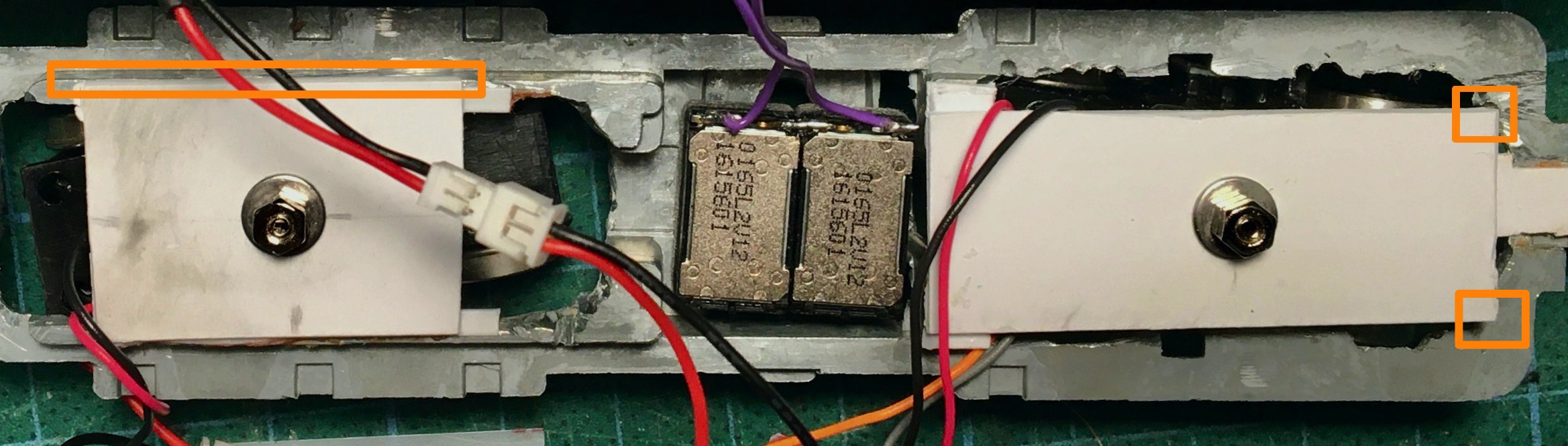
A very pleasant surprise was how nicely the speaker fit into the frame's "fuel area" cavity. BUT - I had a real devil of a time trying to fit the body to the frame! Real bummer. Initially I thought the S-Cab components were somehow preventing the fit, but after a lot of head scratching, I realized the problem was that though tiny, parts of the styrene pieces were protruding past the metal parts of the frame which fit quite snugly up into the body cavity. I had to trim the styrene in the following locations to solve the problem.
Tiny Parts Of Styrene Frame Components Trimmed (Outlined In Orange): On Left, Sliver Removed So That The Edge Did Not Protrude Past The Metal Ridge It Rests On; On Right, Corners Protruded Into Body So Were Removed
After this trimming, I was able to stuff all the S-Cab components into the body, mount it onto the frame, and give it a go.
Here is a video of its maiden run. Pretty Swell! As can be seen, I've remounted the truck frames, trying to be careful of wheel rub.
There was noticeable lurching and obvious wheel slip, which I emailed Neil about. He said that I should run it off rails to check if the mechanism was really not rotating smoothly. First, to reduce variables, I pried off the truck frames. Then I made a mark on one of the wheels and checked, and the wheel rotation was nice and smooth. Neil recommended adding weights. I had lots of old stick-on car weights laying around, but I also ordered
Tungsten weights to try to maximize the weight I could achieve.
A major problem surfaced at this point: The body sat too high on the frame. Mysterious, since I thought I'd checked this. So it was back to further frame work. Checking against an old SW1500 as usual, it looked like the difference was about the width of two of my .060" styrene sheets, taking a "good enough" approach as before.
I first removed the styrene pieces I'd attached to the metal frame, which was not hard since I'd use Goo to attach them. Lowering on the hood end could be accomplished by simply removing the square tubing pieces I'd used to get the body to what I thought would be the right height.
But on the cab end, the metal ridges on either side of the cavity would have to be cut down by half. I used Mr. Dremel again, and a piece of the .060" styrene sheet to gauge the amount of material to be cut off. I gauged the amount to be cut off using a scrap piece of the styrene sheet material, and used the cutting tool as usual to remove metal, trying to keep the resulting surface as flat as I could.
Grinding The Ridges (Hood End), Using A Scrap Piece of .060" Styrene Sheet To Help Determine How Much Metal To Remove
I also noticed that the SDs were sometimes touching the metal frame on the cab end, so I cut out seem of the metal from there also.
Orange Outline Shows Additional Metal Removed Where SDs Were Hanging Up Sometimes
The styrene mount pieces were then reattached to the metal frame. This time the hood end plate would sit on the metal mount points and the styrene T-tab, with a piece of .060" styrene attached to the T-tab to get it to the right height. On the cab end, the L-strip pieces were again glued to their metal ridges, and the mount plate glued directly to them.
This time around I decided to build a wood jig to help with truck positioning. I measured the distance between wheels on one of my other SW1500 models, to use in glueing stops on a piece of wood that would hold the SDs in place with the proper wheel placement. This allowed new to better determine where the holes needed to be located in the styrene mount plates, for the SD mount posts. Here are the SDs positioned in the jig, and the frame and styrene mount fixtures being placed on the SD mount posts.
Jig Built To Help Get The Proper Positioning Of The SDs For The SW1500
This approach, along with the metal frames centerline, allowed the proper placement of the styrene mount plates for final glueing to be much easier to accomplish.
Here, The Jig Is Being Used To Hold The SDs In The Proper Placement Relative To Each Other; The Frame is lowered Over The SDs, And The Mount Plate Locations Marked Where The SD Mount Posts Are Inserted Into The Mount Plate Holes; With The Mount Locations Marked, The Frame Is Removed From The Jig And The Styrene Fixtures Are Glued In Place Using The Marked Mount Locations.
After the glue had dried, I attached the Stanton drives again, making sure that the they were oriented so the red and black power pickup leads were on the same rail for the two trucks. The body was mounted to the frame again, and now the height looked good.
I decided at this point to try to fit the S-Cab's rear light into the body. (I'd removed the original headlight from the model, and found that the S-Cab's front headlight fit well where the old bulb had been.) To install the rear light, I needed to remove the model's plexiglass lens, which I was able to by drilling it out. I used a smaller diameter bit to begin with, then used a bit that matched the inside diameter of the light housing to remove the remaining plexiglass. The S-Cab LEDs fit will into the model's light fixtures. I used small strips of blue masking tape to tape the LED wires to the body's "ceiling" to secure the bulbs.
I started trying to determine how many car weights I could stuff into the body cavity. It took lots of fiddling, and I wold put in weights but find I couldn't get the body to press properly down onto the frame. I finally realized the frame element came up into the body sides further than I originally thought. I finally settled on a setup with four tungsten weights in the cab area, one centered on the frame, and two in the hood cavity. I also stuffed a little wad of lead putty I had laying around between the weights in the cab. The cab end weights impinge up into the visible area of the cab, but not much and it takes work to see them. This photo shows the various weight locations:
Weights Installed Into Body And On Frame
The final weight I able to achieve is 7.87 oz. For comparison, the weight for my Life-Like SW1500 is 8.4 oz, and for another old Athearn SW1500 it's 7.1 oz.
Unfortunately, even with this weight the switcher wheels slip badly. I asked Neil for advice and he suggested trying
Bullfrog Snot, a liquid that is applied to the wheels of a locomotive so that they have some adhesion to the track. Following the directions, I applied snot to three of the four wheels to the powered SD on the cab end. This did the trick!
This video shows the S-Cab at work in the SW1500. A magnetic wand is used to turn the unit on, and the S-Cab throttle used for bell and horn sounds, and to control movement. My shelf layout will only be able to handle trains of three cars and a caboose, and the video shows the loco will handle such just fine.
TBD - further work on side frames
At this point I again tackled attaching the truck side frames to the SDs. I realized the center attachment was not strong, because I'd left some of the original mounting pegs on the side frames, which protruded a bit too much to allow a strong attachment point. So as with the center post, I cut the pegs off using rail nippers and did a bit of filling.
Additional Surgery On Truck Side Frames - Mount Posts To Be Removed (Left), And Removed (Right)
TBD - add Stanton Drive order form above
Project cost (sans shipping and taxes)
NWSL - HO Powered Stanton Drive, 1215, 8'0" WB, 42"/110 Wheels, 2.0mm x 797" flush axle: $84.95
Unpowered Stanton Drive, 1215, 8'0" WB, 42"/110 Wheels, 2.0mm x 797" flush axle: $44.95
TBD - I cut the coupler mounts from the Stanton drives per the instructions.
TBD - Styrene L-angle strip used: .080" 2mm


No comments:
Post a Comment